ALPHEUS Project Work Package 2 – Update
The growing share of intermittent renewable energy sources are creating challenges for grid stability. Energy storage is now becoming an important topic of research to ensure future growth of renewable energy. Reversible pump/turbine technology (RPT) is one of the key areas of research. But many existing RPTs require high head reservoirs which limits application to limited areas in Europe.
The purpose of the ALPHEUS project is to improve RPT technology and the adjacent civil structures needed to make pumped hydro storage economically viable in shallow seas and coastal environments with flat topography.
Proposed PAT Configurations
The project will look at three promising RPT configurations: Shaft-driven variable-speed contra-rotating propeller RPT; Rim-driven variable-speed contra-rotating propeller RPT – rim driven configuration avoids the complexity of a shaft assembly, decreasing noise, vibrations, switching time, and maintenance costs; Positive displacement RPT – fish friendly and seawater-robust, low cost technology. ADT is leading the design optimization efforts on the shaft-driven and rim-driven RPT working together with Chalmers University in Sweden.
Update on Shaft-Driven RPT Design
Initially ADT had to design a 10MW prototype shaft driven and rim driven RPT. The design had to be done completely from scratch given a target head of 9m. Using these conditions in TURBOdesign Pre an initial shaft driven contra-rotating pump was designed with 130m3/s flow rate and rpm of 50 on rotor1 and 45 on the contra-rotating rotor2. The initial meridional shape generated by TURBOdesign Pre was then used to generate 3D geometry of rotor1 and rotor 2 in TURBOdesign1.The resulting stage was analysed in pump mode and turbine mode in CFD. The results showed a very high efficiency of more than 90% (total-total efficiency) in both modes across a range of flow rates. An FEA evaluation showed that the stresses are well within the material limits. A model scale experiment was planned at the test facility at TU Braunschweig to validate the CFD results.
Baseline design was scaled down by a factor of ~22 to a maximum diameter of 276mm; scaling effects reduced efficiency by ~2-3% points. An optimization to improve the stage efficiency and cavitation performance was carried out in model scale. TURBOdesign-Link Workbench was used for a Design of Experiments (DoE) based optimization process. The contra-rotating stage with 2 rotors requires a large number of parameters to describe the stage design. To reduce the computational effort, a sensitivity study is performed initially with 21 TD1 design parameters and a DoE matrix of 35 designs. The design parameters control blade loading, stacking, meridional geometry and speed ratio between rotors. 3 points were evaluated in CFD in each mode for all the designs. From the sensitivity analysis, 11 more sensitive parameters were shortlisted; a detailed DoE study was performed with a design matrix with 95 designs. Performance parameters such as head, power, efficiency and NPSHR were evaluated. From the DoE study results, a Response Surface surrogate model was used to correlate design parameters and performance parameters. An optimization is carried out in Isight software using NSGA-II algorithm; a few optimized design candidates were evaluated in CFD.
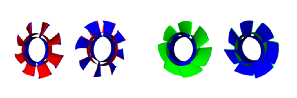
Figure 1.1: Comparison of optimized design (blue) and baseline rotor geometries.
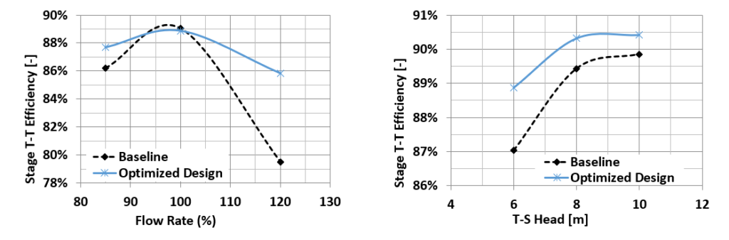
Figure 1.2: Efficiency (total-total) comparison of optimized design and baseline rotor.
Average efficiency improved by 2.6% points in pump mode and 1.1% points in turbine mode is obtained for the optimized design; the minimum head requirement is met in pump mode and NPSHR is improved. Geometry and performance comparison between initial and optimized designs are shown in Fig. 1.1 and Fig. 1.2. Velocity vector comparison in Fig. 1.3 shows that inlet recirculation is absent for optimized design at 85% flow resulting in better performance.
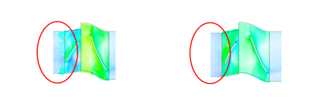
Figure 1.3: Vector plots at 95% span location at 85% flow rate.
Update on Rim-Driven RPT Design
Initial design of the rim driven RPT also followed same procedure as that of shaft driven design, by using TURBOdesign Pre and TURBOdesign1. The rim driven design was found to be less efficient in pump mode in prototype and showed more drop in efficiency in model scale. For design improvement the meridional geometry was made symmetric with hub chord reduced for both rotors. The rotor work coefficient and blade loading were adjusted to keep the diffusion under control. Throat area is adjusted to obtain a design where both the rotors have peak efficiency at the same flow rate. 4 design iterations were performed and the final design gave an average stage efficiency improvement of ~7.7% points in pump mode and 2.8% points in turbine mode. The geometry and efficiency comparison between baseline and optimized designs are shown in Fig. 1.4 and Fig. 1.5 respectively.
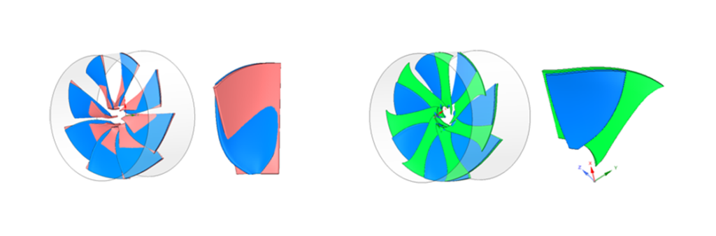
Figure 1.4: Geometry comparison – optimized design (blue) vs baseline.
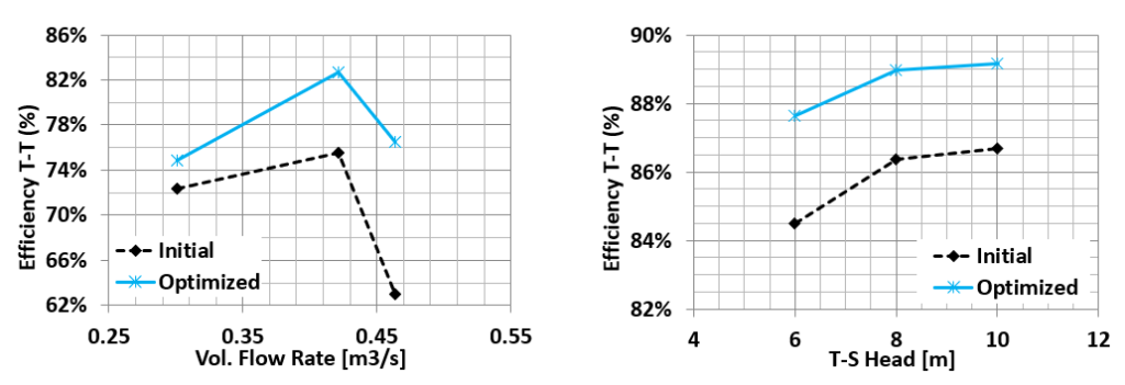
Figure 1.5: Efficiency (total-total) comparison of optimized design and initial rotor.
For further information on ALPHEUS project please refer to www.alpheus-h2020.eu/about