Axial-Flux PMSMs: Detailed 50 kW design
In the ALPHEUS project, the efficiency of the full system is important. Therefore, in WP3, Axial-Flux Permanent Magnet Synchronous Machines (AF-PMSMs) is designed for the full 10 MW design. To validate this design, two ~33 kW AF-PMSMs are designed and developed at Ghent University.
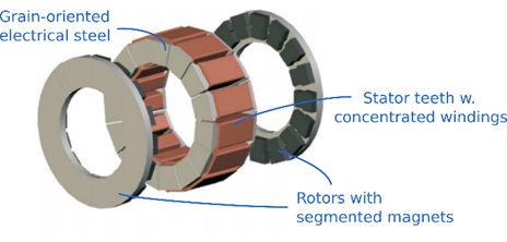
Axial-Flux PMSMs (AF-PMSMs) have a high efficiency, power density and high diameter-to-length ratio. By using a double rotor Yokeless and Segmented Armature (YASA) topology, the predominantly axial magnetic flux path averts the stator yoke, further reducing iron losses and weight. Further efficiency improvements are made by using grain-oriented electrical steel, segmented rotor magnets and concentrated stator windings.
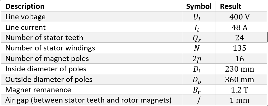
First, the electromagnetic design is performed. The results are shown in in the table below. Note that the number of magnet poles does not match the number of stator teeth. Although this reduces the power of the machine, this is done to limit the cogging torque and torque ripple effect.
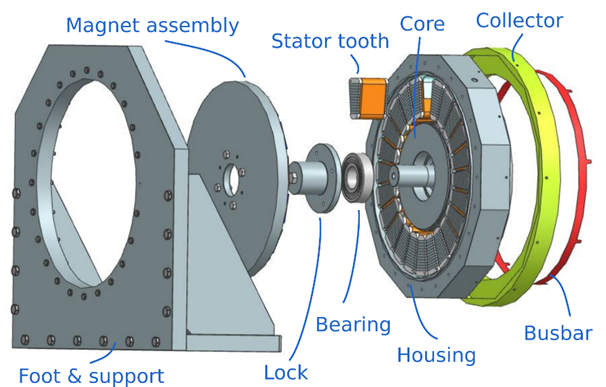
Next, the mechanical design is studied. In the figure below, the full AF-PMSM design is showed in an exploded view. First, the stator is designed. As mentioned, the stator teeth are made of grain-oriented electrical steel. This type of steel exhibits lower magnetic losses in one direction. Because of the unidirectional flux path in this double rotor AF-PMSM, this decreases iron losses. Furthermore, the trapezoidal stator teeth are formed by using small lamella (thickness 0.2 mm), as this drastically reduces eddy currents, again increasing efficiency.
As all stator teeth are in parallel, the current through each stator winding is 6 A. To reach the number of stator windings ( = 135) inside the limited space, a conductor section of 1 mm² is chosen. This results in a resistance of 0.422 Ω per stator teeth and a total of 365 W Joule losses in the stator windings (~1 % efficiency loss). To account for the heat produced because of these losses, internal cooling fins are placed between the stator teeth. These cooling fins direct the heat transfer towards the stator housing.
Next, a stainless steel (nonmagnetic) stator core is designed to house the bearings. The stator housing encompasses the stator teeth and is connected to an aluminium foot and support in order to secure the machine. To connect the stator teeth to the power electronics, they are connected to four busbars (3 phases and one neutral starpoint), which are housed in an insulating collector.
Finally, the rotor is designed. To transfer the radial and axial loads of the inner shaft to the stator, two deep groove ball bearings are used. Next, the magnets are glued to the rotor discs, to form the magnet assembly. As mentioned before, the magnets are segmented into 5 smaller magnets to limit eddy currents and increase efficiency. Note that the magnet assembly is not directly bolted to the inner shaft. Instead, first a ‘Lock’ is bolted to the inner shaft with a central M12 bolt. The reason is twofold: 1) The lock is used to preload the inner ring of the bearings, so that no tolerance exists during operation. 2) Due to the narrow air gap (1 mm), a direct connection would result in a divergence of this air gap, as steel components are always produced with a certain tolerance or error. Therefore, the magnet assembly can be positioned axially by a setting screw. After the exact air gap is reached, four fitting bolts are used to transfer the radial loads and torque.